
HARNESS LAYOUT — Main Harness (Cont'd)
EL-88wiring diagramR.H. Drive Model only. This page shows the R.H. drive variant of the main harness layout. Connector identifiers M2 through M61 are shown with their physical routing positions.
Main Harness (Cont'd)
R.H. DRIVE MODEL
Component LocationFig. fig1
Body ground — upper location (R.H. Drive Model)
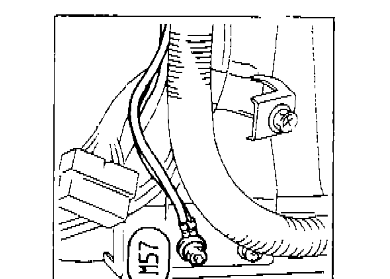
1M57(body ground upper)
2Body ground(left side label)
Component LocationFig. fig2
Body ground — lower location (R.H. Drive Model)
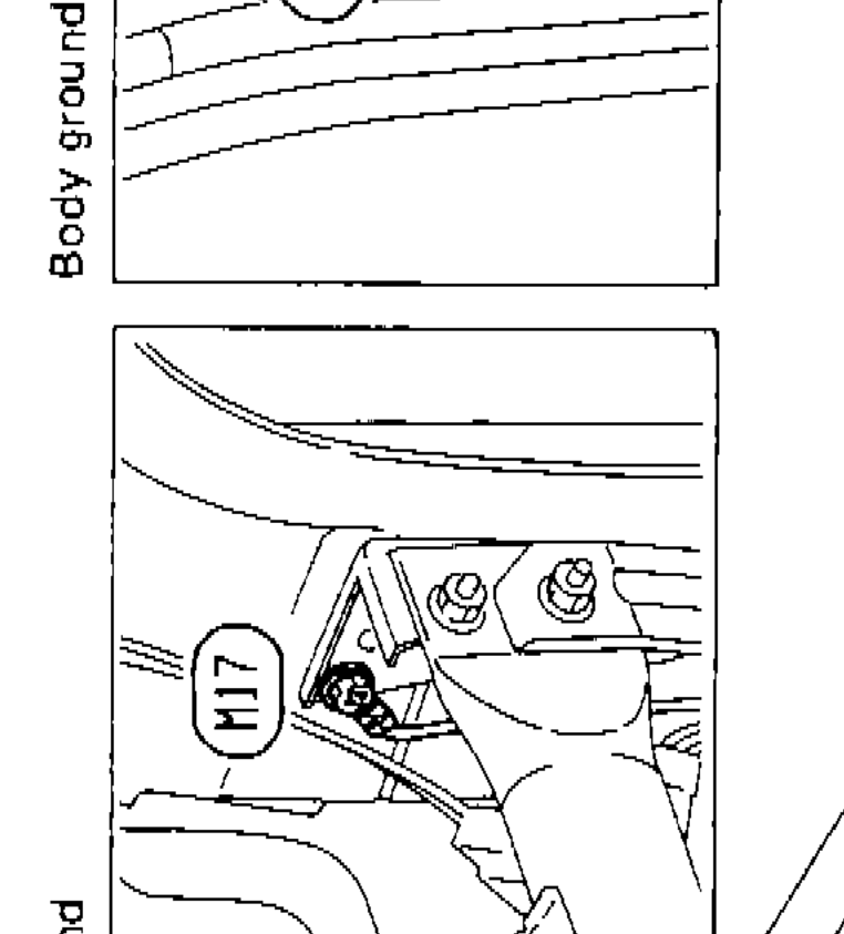
1M17(body ground lower)
2Body ground(left side label)
Component LocationFig. fig3
Main harness connector layout — R.H. Drive Model. All visible connector identifiers:
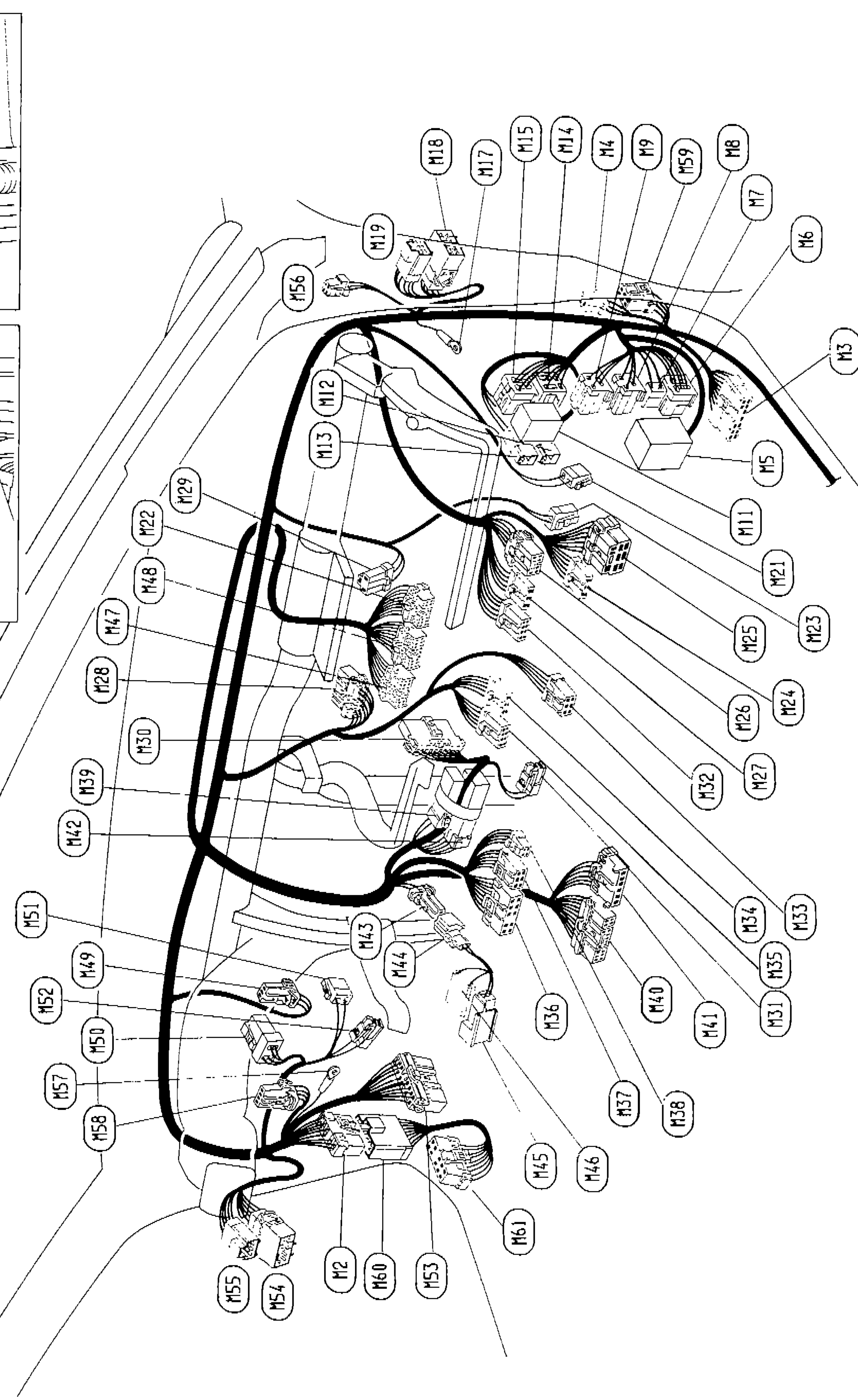
1M2(lower center)
2M3(upper right)
3M4(upper right cluster)
4M5(right center-upper)
5M6(upper far right)
6M7(upper right)
7M8(upper right cluster)
8M9(upper right cluster)
9M11(right center)
10M12(center upper)
11M13(center)
12M14(upper right cluster)
13M15(upper right cluster)
14M17(upper right cluster)
15M18(upper right cluster)
16M19(upper center)
17M21(right center)
18M22(center left-upper)
19M23(right center)
20M24(right center)
21M25(right center)
22M26(right center)
23M27(right center)
24M28(left center)
25M29(center left-upper)
26M30(center left)
27M31(right lower)
28M32(right center-lower)
29M33(right lower)
30M34(right lower)
31M35(right lower)
32M36(center right lower)
33M37(center lower)
34M38(center lower)
35M39(left center)
36M40(right lower center)
37M41(right lower)
38M42(left center)
39M43(center lower)
40M44(center lower)
41M45(lower center)
42M46(lower center)
43M47(left center)
44M48(center left)
45M49(left lower)
46M50(left lower)
47M51(left lower)
48M52(left lower)
49M53(lower center)
50M54(lower left)
51M55(lower left)
52M56(upper center-left)
53M57(left lower)
54M58(left lower)
55M59(upper right cluster)
56M60(lower center)
57M61(lower center)