
HARNESS LAYOUT — Engine Room Harness (Cont'd)
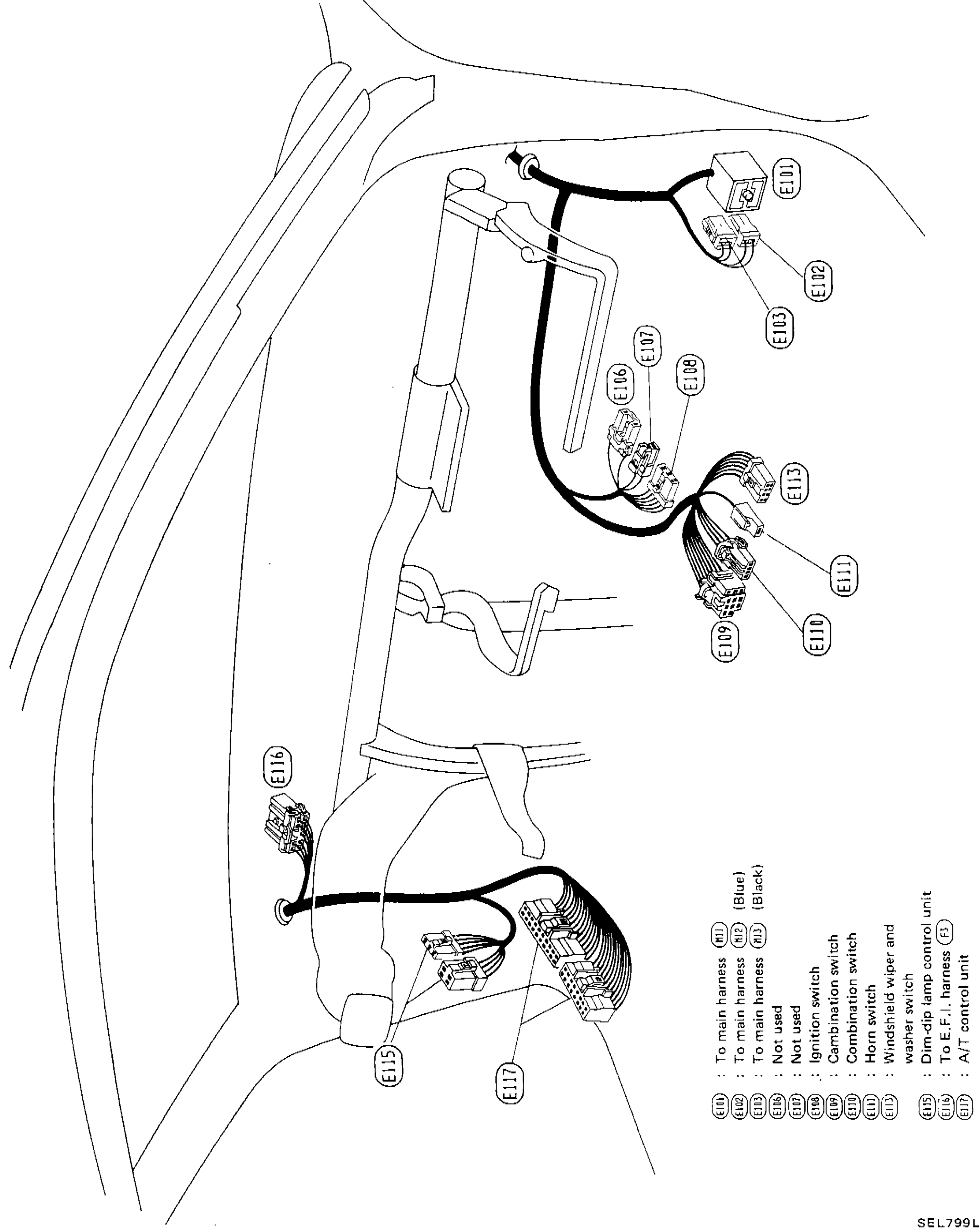
EL-100wiring diagramR.H. Drive Model only. Connectors E101 (Blue), E102 (Blue), E103 (Black) connect to main harness. E104 and E105 are not used. E113 connects to E.F.I. harness (E1). E115/E116/E117 relate to A/T control unit.
Engine Room Harness (Cont'd)
R.H. DRIVE MODEL
Component LocationFig. fig1
Engine room harness connector legend for R.H. Drive Model
SEL799L
1E101(To main harness (E11) (Blue))
2E102(To main harness (E12) (Blue))
3E103(To main harness (E13) (Black))
4E104(Not used)
5E105(Not used)
6E106(Ignition switch)
7E107(Combination switch)
8E108(Combination switch)
9E109(Horn switch)
10E110(Windshield wiper and washer switch)
11E111(Dim-dip lamp control unit)
12E113(To E.F.I. harness (E1))
13E115(A/T control unit)
14E116(A/T control unit)
15E117(A/T control unit)