
LOCATION OF ELECTRICAL UNITS — Engine Compartment
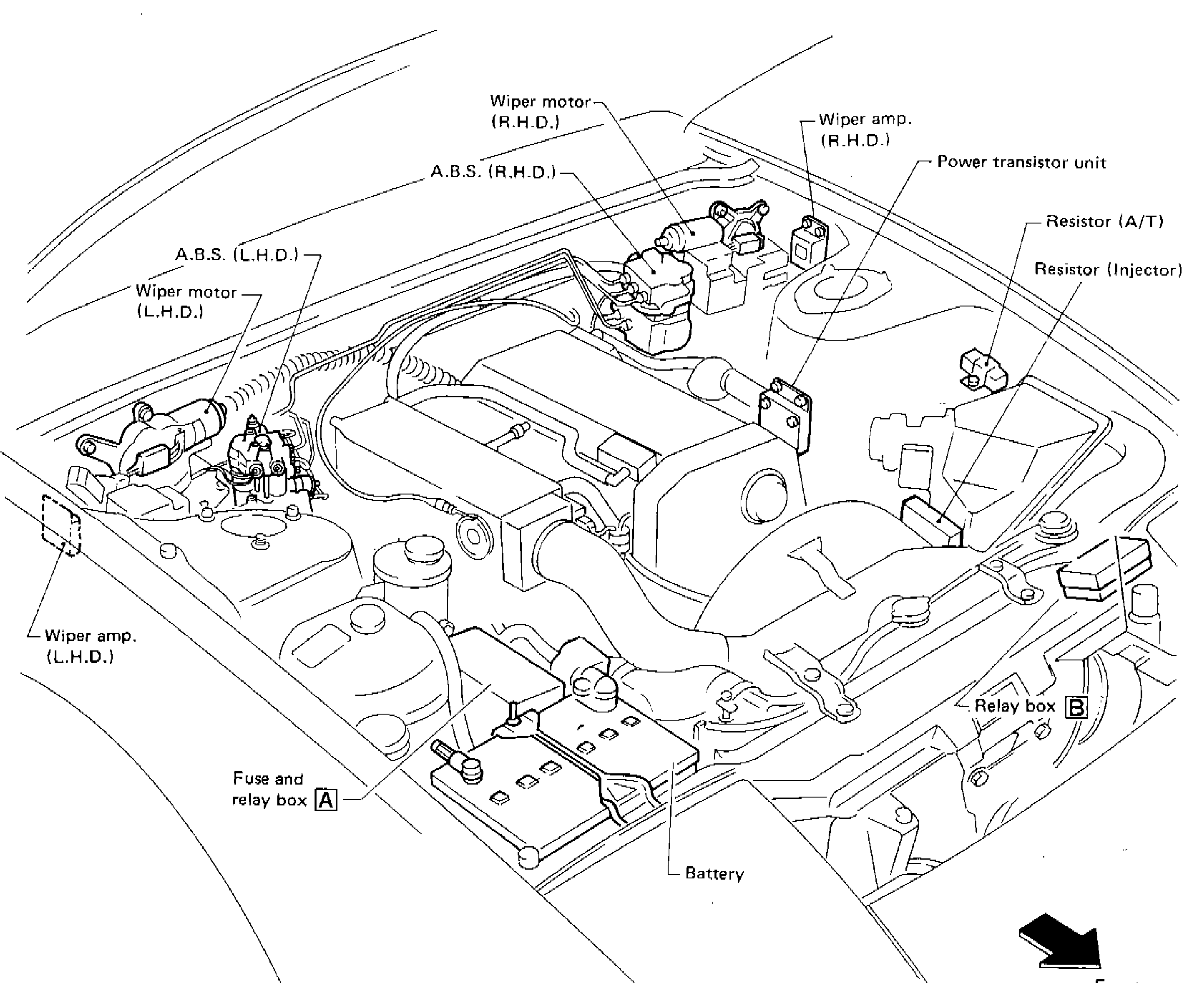
EL-81component photoL.H.D. (Left-Hand Drive) and R.H.D. (Right-Hand Drive) variants noted for wiper motor and wiper amp locations, and A.B.S. positions. Rear fog lamp relay color varies by daytime light system fitment (Blue: Without / Gray: With). Air conditioner relay color varies by market (Blue: For Europe / Brown: Except for Europe). Inhibitor relay (Blue) is specific to A/T models.
Engine Compartment
Component LocationFig. fig1
Engine compartment electrical unit locations
SEL705L
1Wiper motor (R.H.D.)(upper center)
2Wiper amp. (R.H.D.)(upper right)
3A.B.S. (R.H.D.)(upper center-left)
4Power transistor unit(right)
5Resistor (A/T)(right)
6Resistor (Injector)(right)
7A.B.S. (L.H.D.)(upper left)
8Wiper motor (L.H.D.)(left)
9Wiper amp. (L.H.D.)(lower left)
10Fuse and relay box A(lower center-left)
11Battery(lower center)
12Relay box B(lower right)
13Front(far right (direction arrow))
Component LocationFig. fig2
Fuse and relay box A — relay and fuse identification
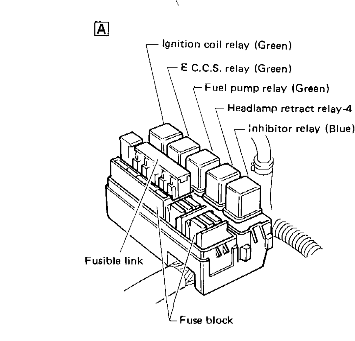
1Ignition coil relay (Green)(top)
2E.C.C.S. relay (Green)(upper)
3Fuel pump relay (Green)(middle-upper)
4Headlamp retract relay-4 (Gray)(middle)
5Inhibitor relay (Blue)(middle-lower)
6Fusible link(lower left)
7Fuse block(bottom)
Component LocationFig. fig3
Relay box B — relay identification
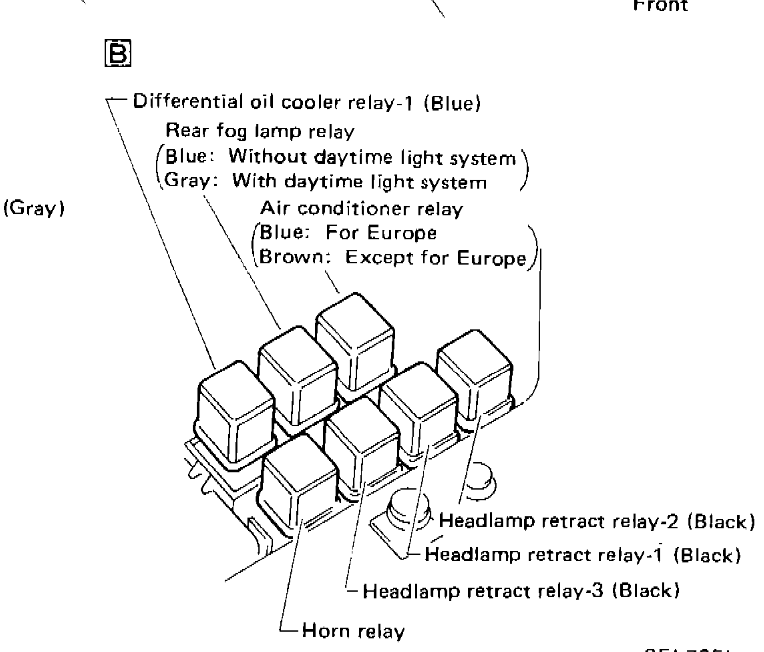
1Differential oil cooler relay-1 (Blue)(top)
2Rear fog lamp relay — Blue: Without daytime light system / Gray: With daytime light system(upper)
3Air conditioner relay — Blue: For Europe / Brown: Except for Europe(middle)
4Headlamp retract relay-2 (Black)(lower right)
5Headlamp retract relay-1 (Black)(lower center-right)
6Headlamp retract relay-3 (Black)(lower center)
7Horn relay(bottom left)