
HARNESS LAYOUT — E.F.I. Harness (L.H.D.)
EL-102component photoUnverifiedConnector legend continues on EL-103.
E.F.I. Harness
L.H. DRIVE MODEL
NOTE
Pictorial map of the E.F.I. (CA18DET) loom with connector callouts F1–F32 plus the ignition-coil sub-harness (F101–F106). Two engine-ground insets identify the physical grounding locations near the block.
Component LocationFig. fig1
L.H.D. E.F.I. harness connector locations.
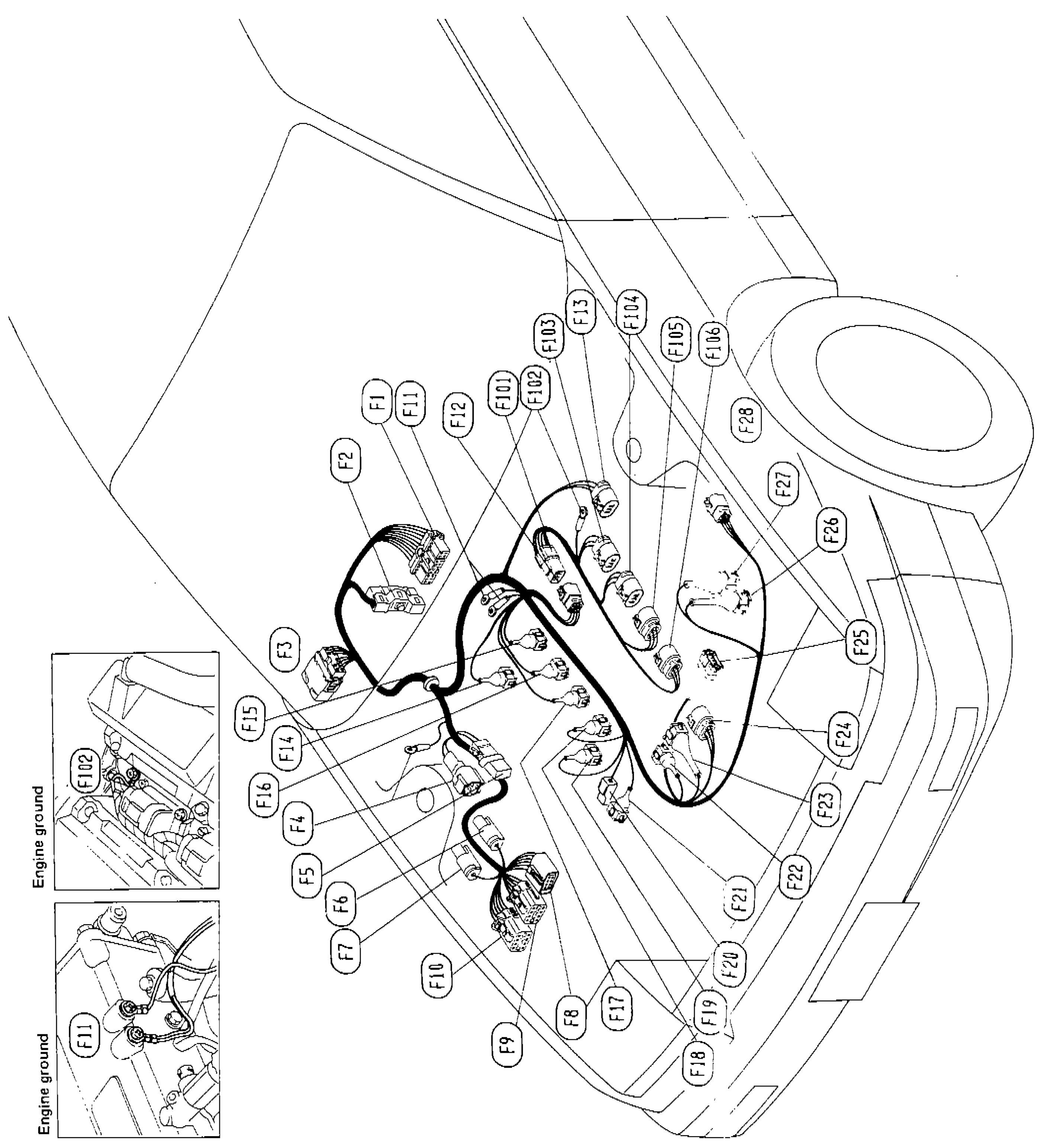
1Engine ground (×2 insets)(Lower-left of figure)
2Main-harness pass-through (F1 / F2 / F3)(Bulkhead)
3ECCS control unit pass-through(Cabin side)
4Injector cluster (F14–F17)(Top of cam cover)
5Ignition coil sub-harness (F101–F106)(Coil pack area)
6Throttle-body / TPS / IAC cluster (F19–F23)(Throttle body)
7Air-flow meter / engine-temp sensor(Intake side)