
ANTI-LOCK BRAKING SYSTEM — System Components, Hydraulic Circuit
BR-32parts diagramA.B.S. fitted only on the higher-trim 200SX variants (paired with the CL25VA front caliper).
System Components
Component LocationFig. fig1
A.B.S. component layout on the vehicle.
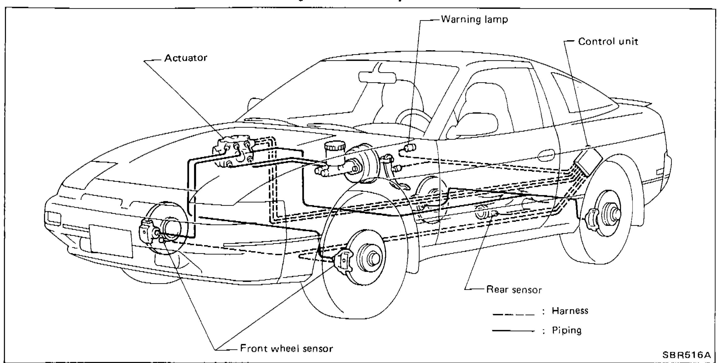
SBR516A
1Actuator(Under bonnet)
2Warning lamp(Dashboard)
3Control unit(Behind dashboard)
4Front wheel sensor(Front-wheel hub)
5Rear sensor(Rear axle)
Hydraulic Circuit
A.B.S. hydraulic circuit
Components (23)
Master cylinderBrake boosterProportioning valve (do not disassemble)A.B.S. actuator (assembly enclosing the valves, pumps, accumulator, reservoirs and motor below)Solenoid valve (Front L.H.)Solenoid valve (Front R.H.)Solenoid valve (Rear)Check valve (Front L.H.)Check valve (Front R.H.)Check valve (Rear)Relief valve (Front)Relief valve (Rear)Feeling valve (Front)Feeling valve (Rear)AccumulatorPump (Front)Pump (Rear)D.C. motorReservoir (Front)Reservoir (Rear)Caliper — Front R.H.Caliper — Front L.H.Caliper — Rear R.H.