
CRANKCASE EMISSION CONTROL SYSTEM
EF & EC-134prose procedureDescription
Component LocationFig. fig1
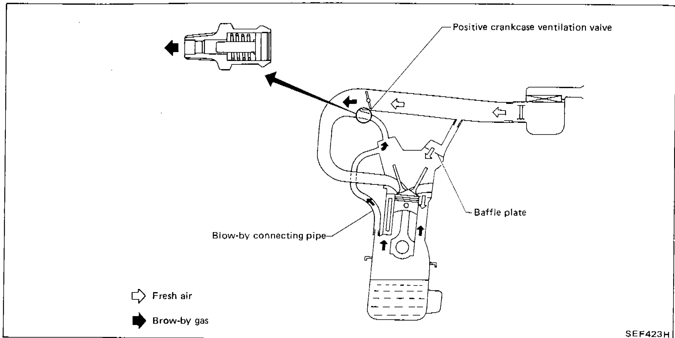
Crankcase emission control system diagram showing component locations and gas flow paths
SEF423H
1Positive crankcase ventilation valve(top-right)
2Baffle plate(center-right)
3Blow-by connecting pipe(center-left)
4Fresh air(bottom-left)
5Blow-by gas(bottom-left)
This system returns blow-by gas to the intake manifold.
The positive crankcase ventilation (P.C.V.) valve is provided to conduct crankcase blow-by gas to the intake manifold.
During partial throttle operation of the engine, the intake manifold sucks the blow-by gas through the P.C.V. valve.
Normally, the capacity of the valve is sufficient to handle any blow-by and a small amount of ventilating air.
The ventilating air is then drawn from the air cleaner, through the hose connecting air inlet to rocker cover, into the crankcase.
Under full-throttle condition, the manifold vacuum is insufficient to draw the blow-by flow through the valve, and its flow goes through the hose connection in the reverse direction.
On vehicles with an excessively high blow-by some of the flow will go through the hose connection to the air inlet under all conditions.
Inspection
P.C.V. (Positive Crankcase Ventilation) VALVE
P.C.V. Valve Inspection
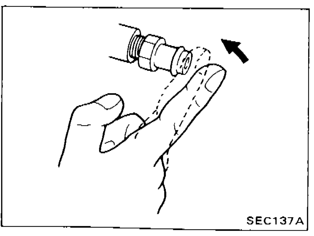
- 1With engine running at idle, remove ventilation hose from P.C.V. valve; if valve is working properly, a hissing noise will be heard as air passes through it and a strong vacuum should be felt immediately when a finger is placed over valve inlet.
 SEC137A