
TROUBLE DIAGNOSES — Diagnostic Procedure 14: AIR REGULATOR (Not self-diagnostic item)
EF & EC-110wiring diagramL.H. drive mode and R.H. drive mode variants noted on wiring schematic. Connector routing may differ between drive modes.
Diagnostic Procedure 14
AIR REGULATOR (Not self-diagnostic item)
Air Regulator Wiring Schematic
Components (19)
E.C.C.S. CONTROL UNITConnector F2Connector F22AIR REGULATORFUEL PUMP RELAYConnector E16Connector E108IGNITION SWITCHFUSEFUSIBLE LINKFUSE AND FUSIBLE LINK (In RELAY BOX)Connector E22Connector F10 (Brown)Connector E10Connector F19ENGINE GROUNDBATTERYE.F.I. harnessEngine room harness
Connections (10)
E.C.C.S. CONTROL UNIT
E.C.C.S. CONTROL UNITAIR REGULATORB/P— 18-B/P
Connector F22
Connector F22E.F.I. harnessB/P
E.F.I. harness
E.F.I. harnessEngine room harnessB/P
E.F.I. harnessEngine room harnessB/Y
FUEL PUMP RELAY
FUEL PUMP RELAYIGNITION SWITCHB/R
IGNITION SWITCH
IGNITION SWITCHFUSEB/R
FUSE
FUSEFUSE AND FUSIBLE LINK (In RELAY BOX)B/W
FUSE AND FUSIBLE LINK (In RELAY BOX)
FUSE AND FUSIBLE LINK (In RELAY BOX)BATTERYW
Connector E22
Connector E22BATTERY— ground connection
ENGINE GROUND
ENGINE GROUNDBATTERY— ENGINE GROUND
NOTE
L : L.H. drive mode
R : R.H. drive mode
Component LocationFig. fig2
Engine bay photograph indicating the physical location of the Air Regulator.
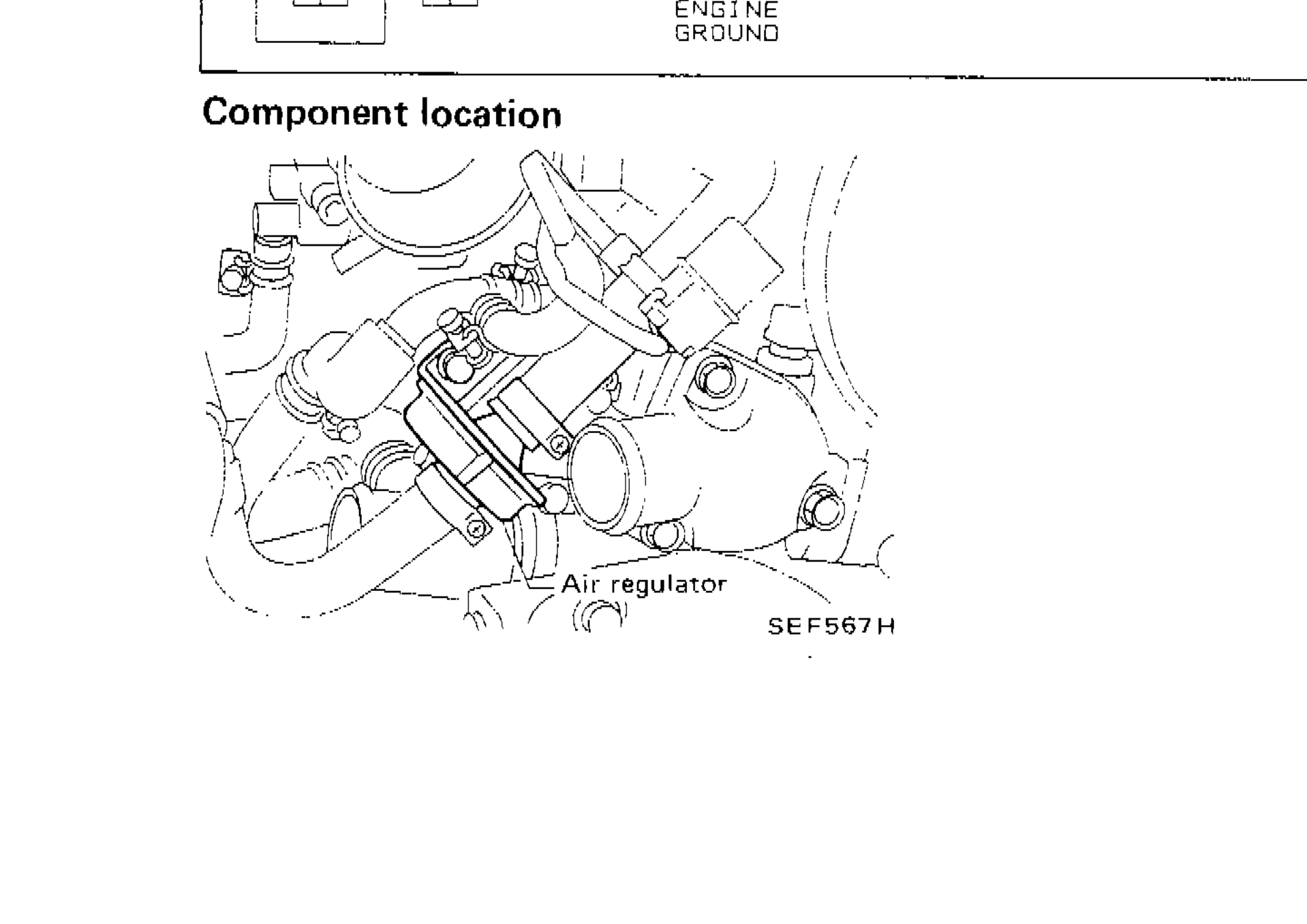
SEF567H
1Air regulator(center-lower area of engine bay photo)