
EVAPORATIVE EMISSION CONTROL SYSTEM (For catalyzer model) — Inspection (Cont'd)
EF & EC-133prose procedureFor catalyzer (catalyst) model only
Inspection (Cont'd)
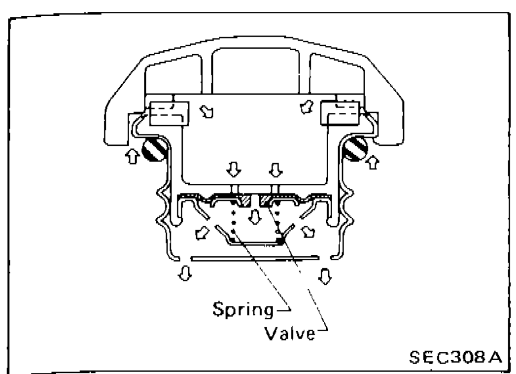
FUEL TANK VACUUM RELIEF VALVE
- 1Wipe clean valve housing.
 SEC308A
 - 2Inhale air through the cap. A slight resistance accompanied by valve clicks indicates that valve is in good mechanical condition. Note also that, by further inhaling air, the resistance should disappear with valve clicks.
- 3If valve is clogged or if no resistance is felt, replace cap as an assembly.
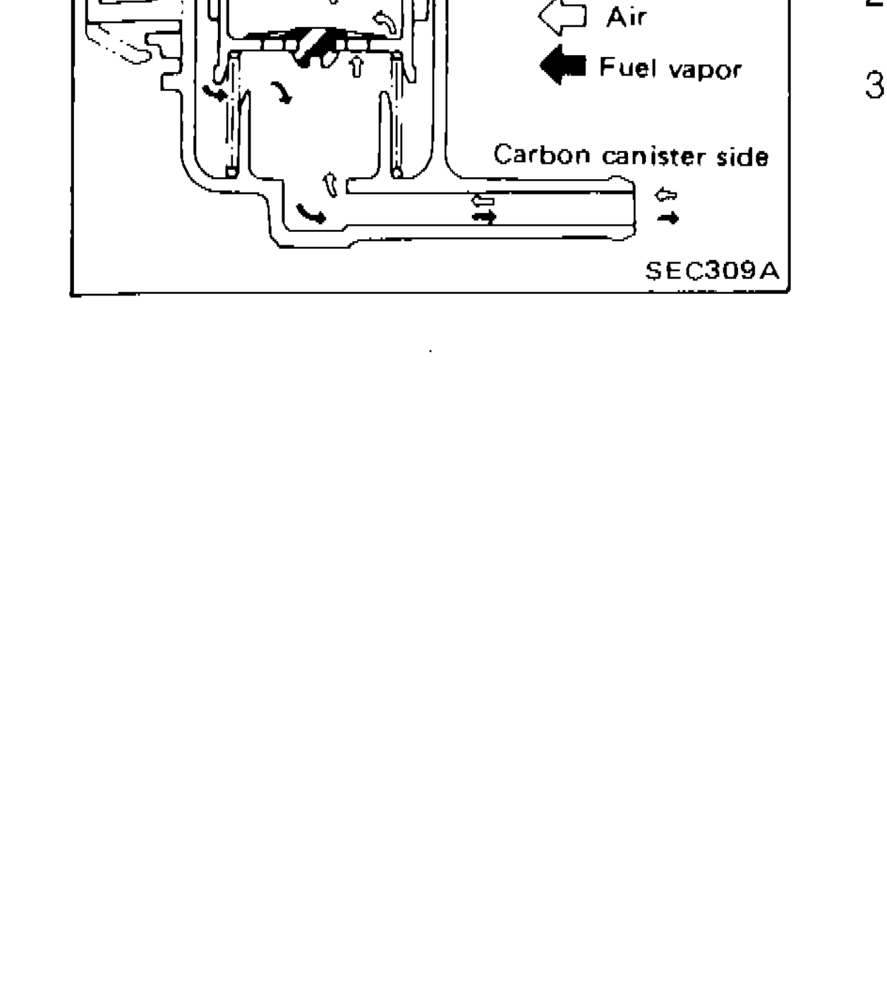
FUEL CHECK VALVE
- 1Blow air through connector on fuel tank side. A considerable resistance should be felt and a portion of air flow should be directed toward the canister.
 SEC309A
 - 2Blow air through connector on canister side. Air flow should be smoothly directed toward fuel tank.
- 3If fuel check valve is suspected of not properly functioning in steps 1 and 2 above, replace it.
Parts DiagramFig. fig1
Component LocationFig. fig2
Fuel check valve showing flow directions between fuel tank side and carbon canister side
1Fuel tank side(top-right of valve body)
2Air(middle, arrow pointing right)
3Fuel vapor(middle, arrow pointing left (filled))
4Carbon canister side(bottom-right of valve body)