
TROUBLE DIAGNOSES — Electrical Components Inspection (Cont'd)
AT-66prose procedureApplies to A/T (automatic transmission) equipped vehicles only.
Electrical Components Inspection (Cont'd)
INHIBITOR SWITCH
Inhibitor Switch Inspection
- 1Check continuity between terminals 1 and 2 and between terminals 3 and 4, 5, 6, 7, 8, 9 while moving selector lever through each range.
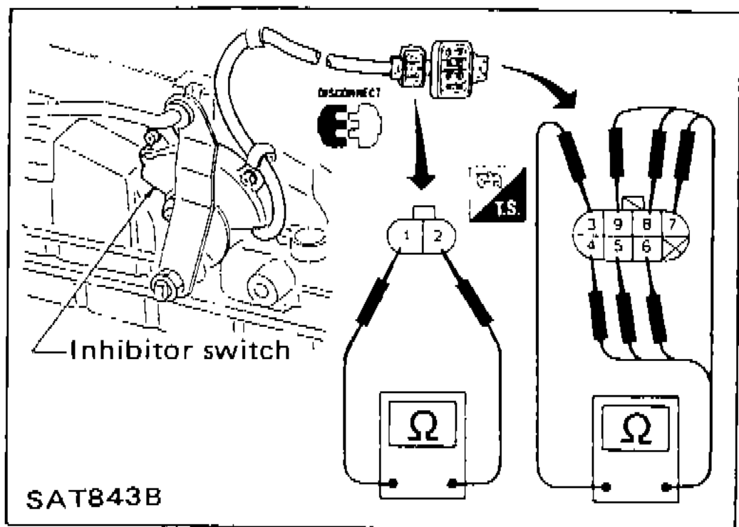 SAT843B
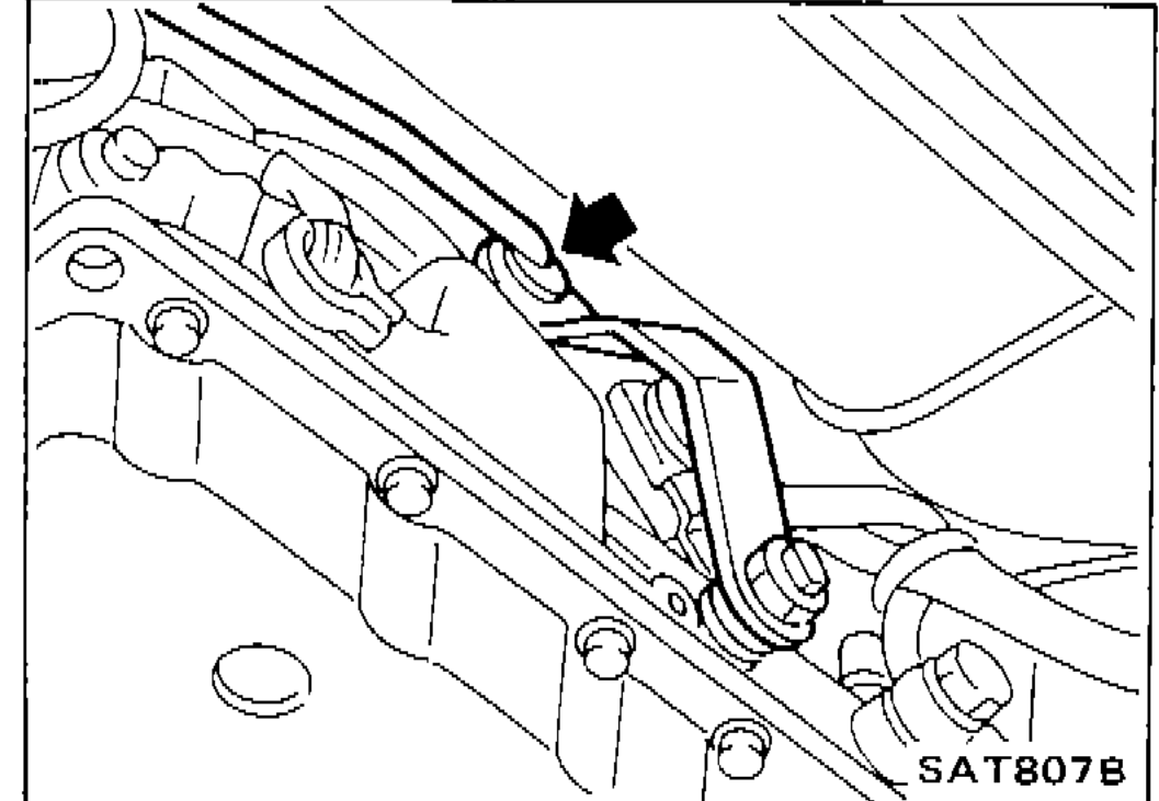
 - 2If N.G., check again with manual control linkage disconnected from manual shaft of A/T assembly. — Refer to step 1.
 SAT807B
 - 3If O.K. on step 2, adjust manual control linkage. — Refer to "ON-VEHICLE SERVICE".
- 4If N.G. on step 2, remove inhibitor switch from A/T and check continuity of inhibitor switch terminal. — Refer to step 1.
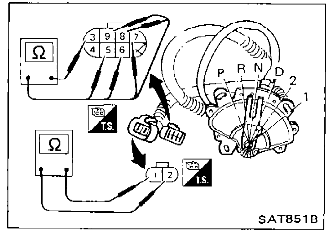 SAT851B
 - 5If O.K. on step 4, adjust inhibitor switch. — Refer to "ON-VEHICLE SERVICE".
- 6If N.G. on step 4, replace inhibitor switch.
Inhibitor Switch Terminal Continuity — Lever Position vs Terminal No.
P
1o
2o
3o
4o
5
6
7
8
9
R
1
2
3o
4
5o
6
7
8
9
N
1o
2o
3o
4
5
6o
7
8
9
D
1
2
3o
4
5
6
7o
8
9
2
1
2
3o
4
5
6
7
8o
9
1
1
2
3o
4
5
6
7
8
9o
REVOLUTION SENSOR
For removal and installation, refer to "ON-VEHICLE SERVICE".
Check resistance between terminals 1, 2 and 3.
Revolution Sensor Resistance
1
Terminal No.2
Resistance500 - 650Ω
2
Terminal No.3
ResistanceNo continuity
1
Terminal No.3
ResistanceNo continuity
See also
ON-VEHICLE SERVICE