
ASSEMBLY — Gear Components (Cont'd)
MT-21prose procedureGear Components (Cont'd)
- fPress counter drive gear with main drive gear with Tool.Pay attention to direction of counter drive gear.
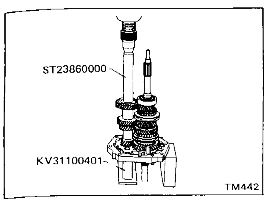 TM442
TM442 - gInstall sub-gear components.
- Install sub-gear and sub-gear bracket on counter drive gear and then select proper snap ring to minimize clearance of groove in counter gear. Allowable clearance of groove: 0 - 0.18 mm (0 - 0.0071 in). Counter drive gear snap ring: Refer to S.D.S.
- Remove snap ring, sub-gear bracket and sub-gear from counter gear.
- Reinstall sub-gear, sub-gear spring and sub-gear bracket.
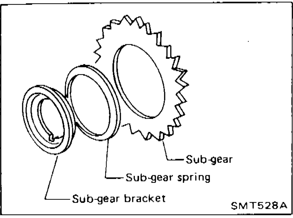 SMT528A
 - hInstall selected counter drive gear snap ring.
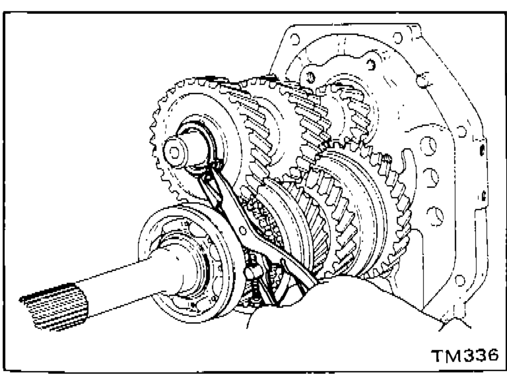 TM336
TM336 - iPress counter gear front bearing onto counter gear.
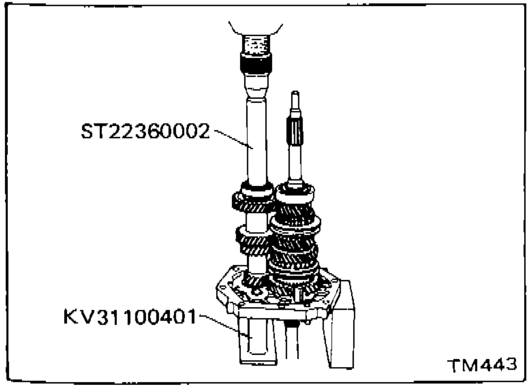 TM443
TM443
IMPORTANT
Pay attention to direction of counter drive gear.
| Specification | Value |
|---|---|
| Allowable clearance of groove (counter drive gear)Sub-gear and sub-gear bracket installed on counter drive gear | 0 - 0.18mm0 - 0.0071in |
Allowable clearance of groove (counter drive gear)Sub-gear and sub-gear bracket installed on counter drive gear
0 - 0.18mm0 - 0.0071in
Parts DiagramFig. fig3
See also
S.D.S.