
DISASSEMBLY — Shift Control Components (Cont'd) & Gear Components
MT-12prose procedureShift Control Components (Cont'd)
- 7Draw out O.D. and reverse fork shaft by rotating O.D. and reverse bracket counterclockwise.
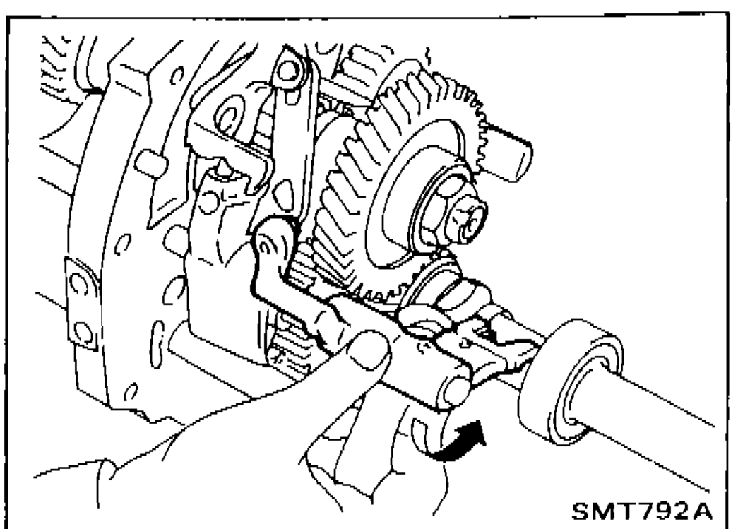 SMT792A
Gear Components
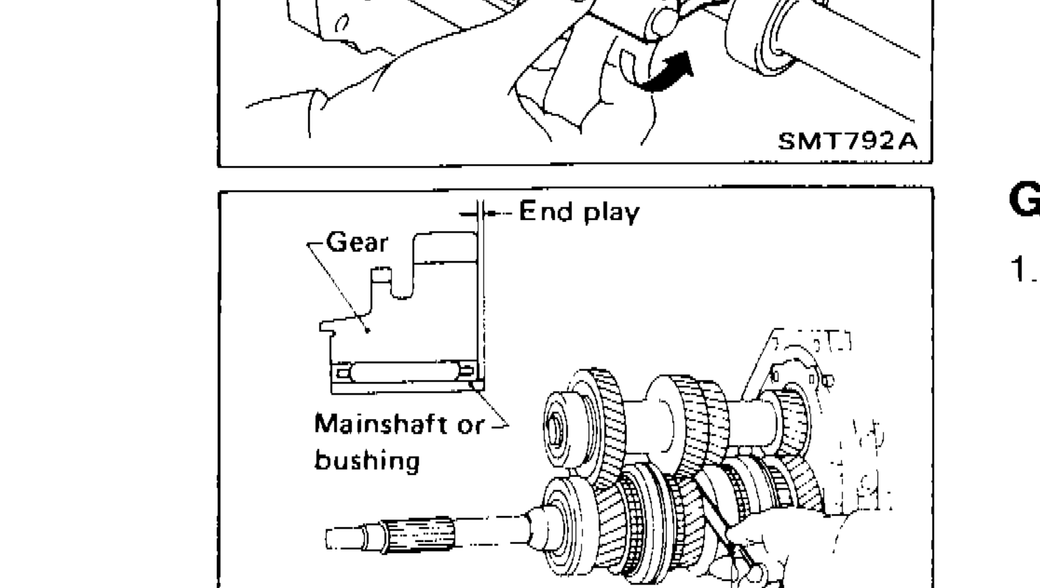
- 1Before removing gears and shafts, measure each gear end play. Gear end play: Refer to S.D.S. If not within specification, disassemble and check contact surface of gear to hub, washer, bushing, needle bearing and shaft.Gear end play: Refer to S.D.S.
 SMT025
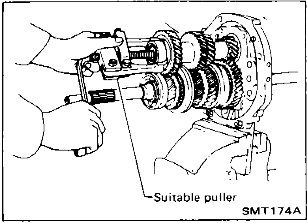
 - 2Mesh 2nd and reverse gear, then draw out counter front bearing with suitable puller.
 SMT174A
 - 3Remove snap ring and then remove sub-gear bracket, sub-gear spring and sub-gear.
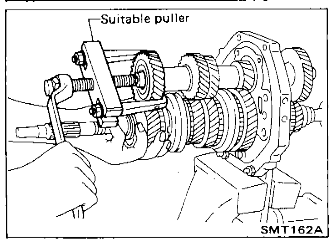
- 4Draw out counter drive gear with main drive gear assembly with suitable puller.When drawing out main drive gear assembly, be careful not to drop pilot bearing and baulk ring.
 SMT162A
 - 5Remove rear side components on mainshaft and counter gear.
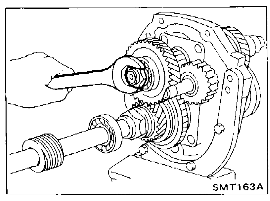 SMT163A
 - 5aRelease staking on countershaft nut and mainshaft nut and loosen these nuts. Mainshaft nut: Left-hand threadMainshaft nut: Left-hand thread
See also
S.D.S.