
STEERING WHEEL AND STEERING COLUMN — Disassembly and Assembly (Cont'd)
ST-13prose procedureTilt-lever adjustment procedure applies to R.H.D. cars only.
Disassembly and Assembly (Cont'd)
IMPORTANT
When disassembling and assembling, unlock steering lock with key.
Ensure that rounded surface of snap ring faces toward bearing when snap ring is installed.
Install snap ring ① before inserting shaft into jacket tube.
Install snap ring on upper shaft with box wrench.
Tilt mechanism (Jumping tilt only)
Tilt-mechanism setup and check
- 1Tighten adjusting nut to specification.
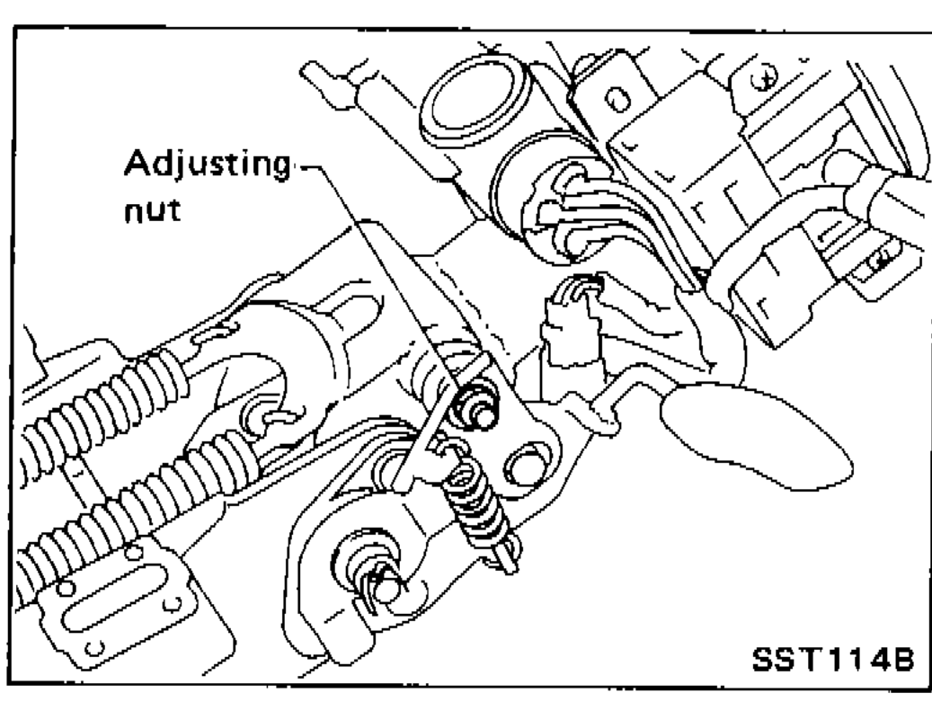 SST114B
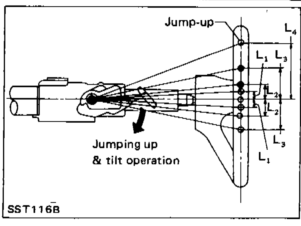
 - 2After installing steering column, check tilt mechanism operation.
 SST116B
| Specification | Value |
|---|---|
| Tilt adjusting nutStep a). | ≈39 - 49N·m |
| Tilt operation length L (position 1)Tilt jump-up check. | 9.8mm (0.386 in) |
| Tilt operation length L (position 2)Tilt jump-up check. | 19.5mm (0.768 in) |
| Tilt operation length L (position 3)Tilt jump-up check. | 29.3mm (1.154 in) |
| Tilt operation length L (position 4)Tilt jump-up check. | 58.2mm (2.291 in) |
Tilt adjusting nutStep a).
39 - 49N·m
Tilt operation length L (position 1)Tilt jump-up check.
9.8mm (0.386 in)
Tilt operation length L (position 2)Tilt jump-up check.
19.5mm (0.768 in)
Tilt operation length L (position 3)Tilt jump-up check.
29.3mm (1.154 in)
Tilt operation length L (position 4)Tilt jump-up check.
58.2mm (2.291 in)
Adjust tilt lever (R.H.D. tilt only)
Tilt-lever adjustment (R.H.D. only)
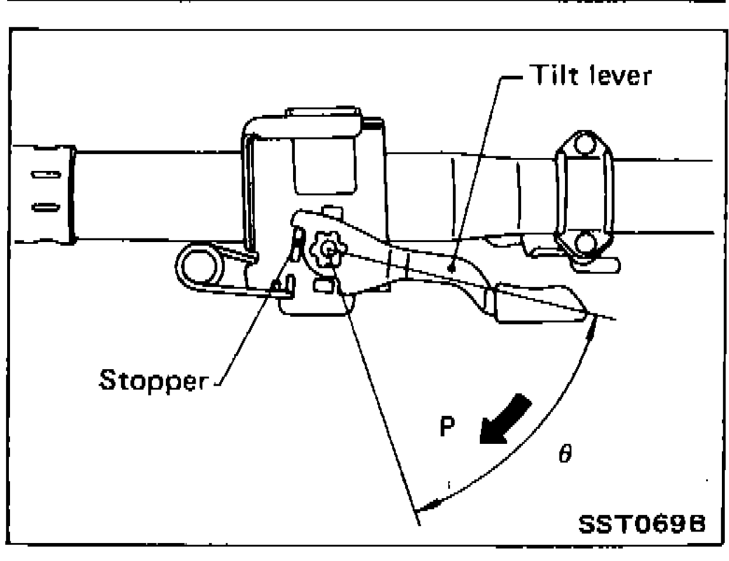
- 1When tilt lever contacts stopper, tighten adjusting bolt securely.
 SST069B
 - 2Turn tilt lever by 90° (θ) in direction "P" to check that steering column moves smoothly without binding.
- 3Return tilt lever to position θ. Make sure there is no free play (= 0) of steering column when steering wheel is pushed down by force.
- 4Install lock washer and E-ring.