ENGINE LUBRICATION SYSTEM — Oil Pump (Cont'd), Oil Jet, Turbocharger
LC-6prose procedureTurbocharger section applicable to CA18DET turbocharged engine variant only.
Oil Pump (Cont'd)
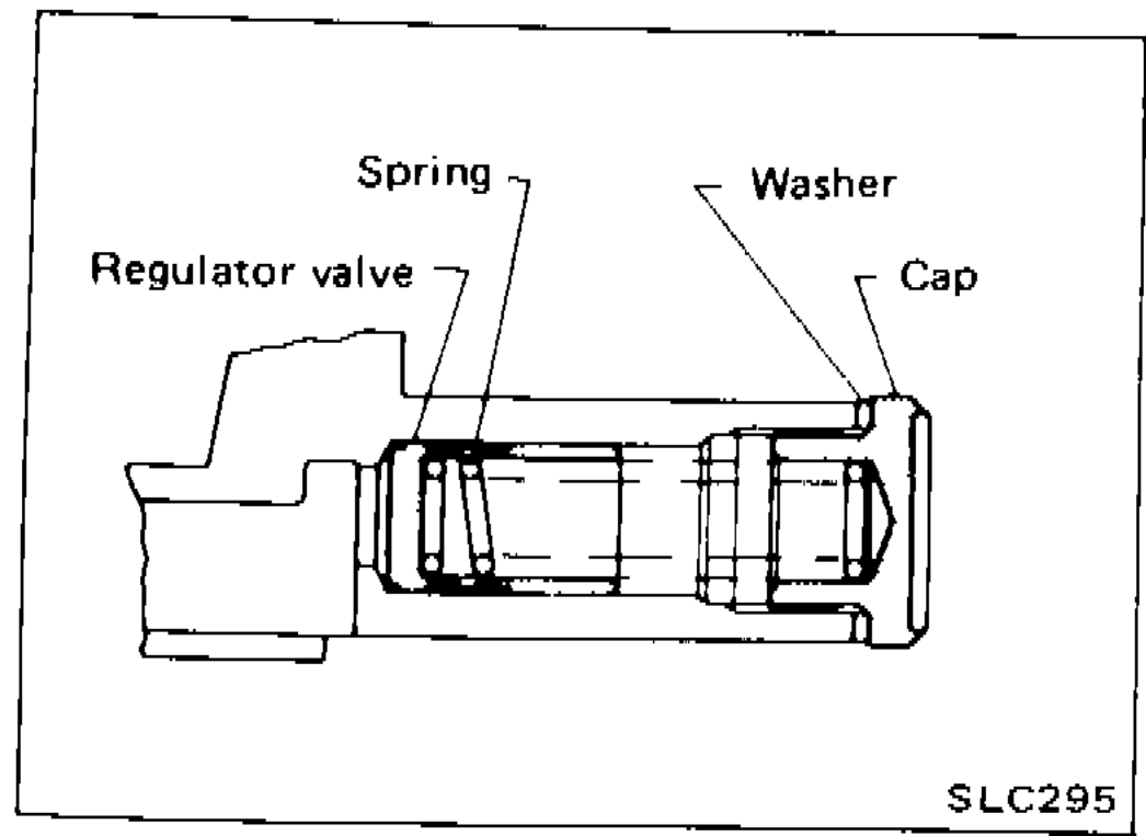
REGULATOR VALVE INSPECTION
- 1Visually inspect components for wear and damage.
 SLC295
 - 2Check oil pressure regulator valve sliding surface and valve spring.
- 3Coat regulator valve with engine oil and check that it falls smoothly into the valve hole by its own weight.
IMPORTANT
If damaged, replace regulator valve set or oil pump assembly.
OIL PRESSURE RELIEF VALVE INSPECTION
Inspect oil pressure relief valve for movement, cracks and breaks by pushing the ball. If replacement is necessary, remove valve by prying it out with a suitable tool. Install a new valve in place by tapping it.
Oil Jet
INSPECTION (For piston)
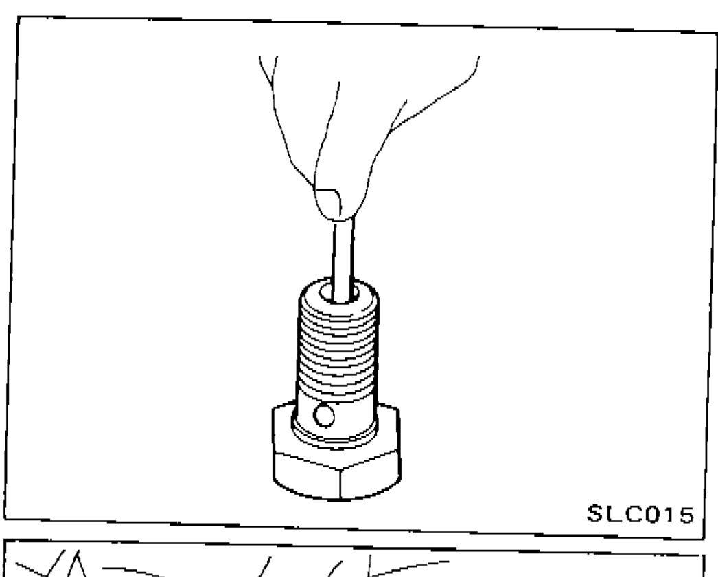
- 1Blow through outlet of oil jet and make sure that air comes out of inlet.
 SLC015
 - 2Push cut-off valve of oil jet bolt with a clean resin or brass rod and make sure that cut-off valve moves smoothly with proper repulsion.
NOTE
When installing oil jet, align oil jet's boss with hole on cylinder block.
| Specification | Value |
|---|---|
| Oil jet bolt | 29 - 39N·m |
Oil jet bolt
29 - 39N·m
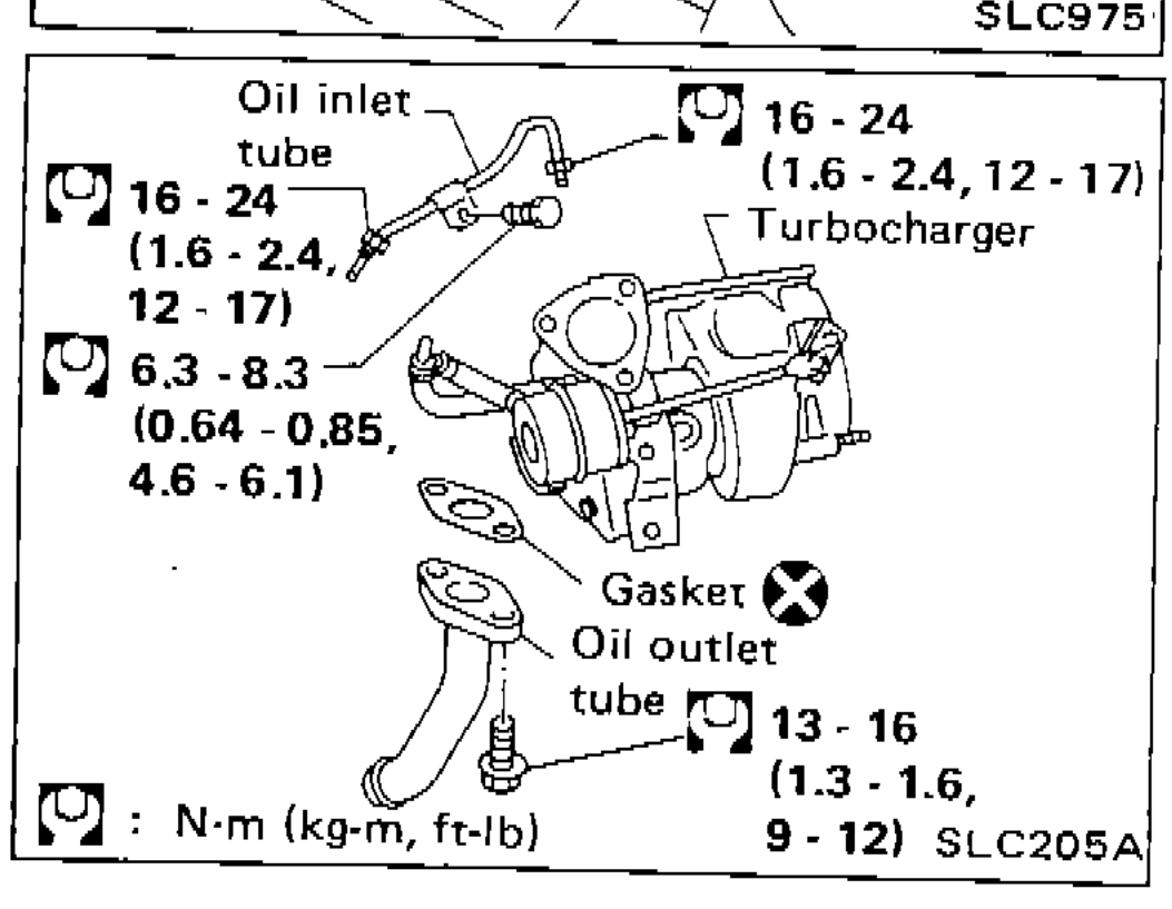
Turbocharger
CAUTION
Before removing water tube, drain coolant first.
NOTE
After installation, run engine for a few minutes and check for leaks.
| Specification | Value |
|---|---|
| Oil inlet tube bolt | 16 - 24N·m |
| Oil inlet tube (small bolt) | 6.3 - 8.3N·m |
| Turbocharger mounting bolt | 16 - 24N·m |
| Oil outlet tube bolt | 13 - 16N·m |
Oil inlet tube bolt
16 - 24N·m
Oil inlet tube (small bolt)
6.3 - 8.3N·m
Turbocharger mounting bolt
16 - 24N·m
Oil outlet tube bolt
13 - 16N·m
Parts DiagramFig. fig1
Parts DiagramFig. fig4