
CHECK AND ADJUSTMENT — On-vehicle: Front Wheel Alignment (Cont'd)
FA-7prose procedureFront Wheel Alignment (Cont'd)
| Specification | Value |
|---|---|
| Caster | 5°55' - 7°25'degrees/minutes |
| Camber | -1°25' to 5'degrees/minutes |
Caster
5°55' - 7°25'degrees/minutes
Camber
-1°25' to 5'degrees/minutes
If camber is not within specification, adjust by turning adjusting pin as follows:
Camber Adjustment Procedure
- 1Remove adjusting pin. Adjusting pin is installed with flat portion facing downward.Adjusting pin is installed with flat portion facing downward.
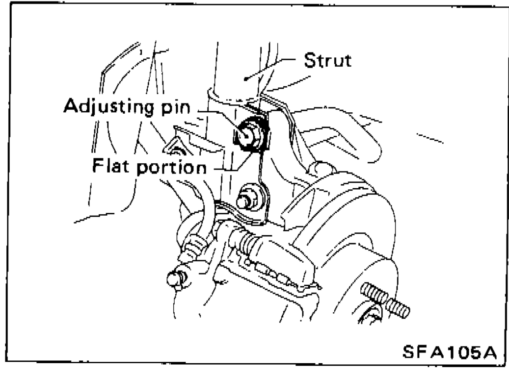 SFA105A
 - 2Next replace adjusting pin with flat portion facing upward.
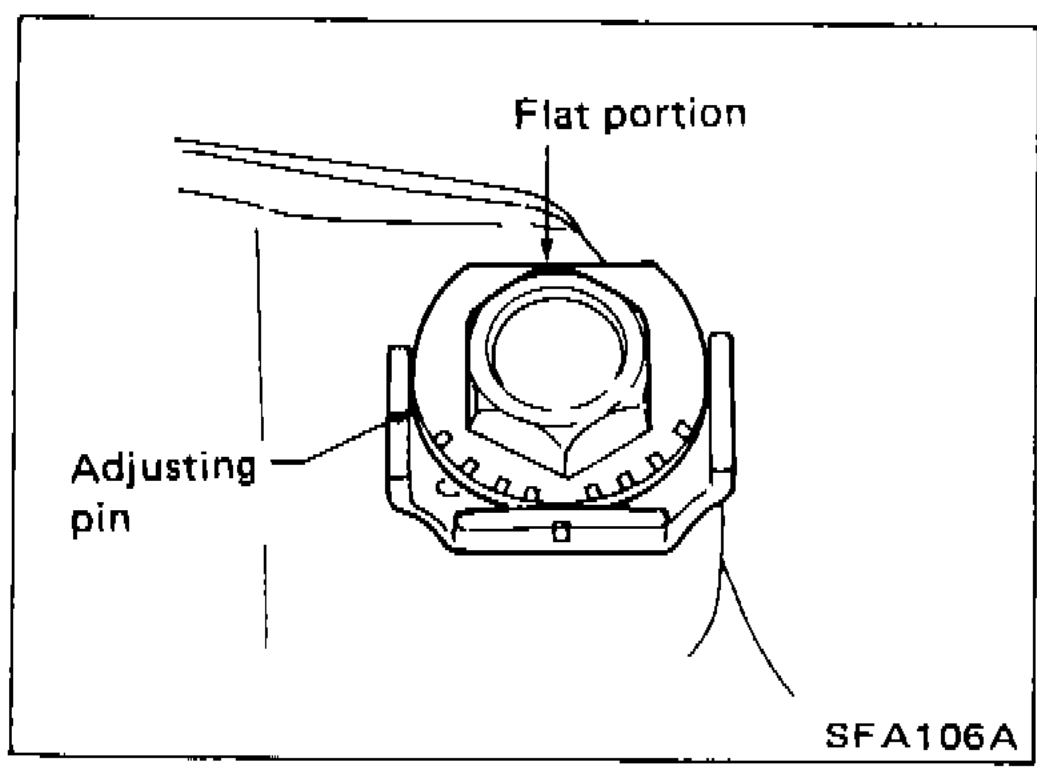 SFA106A
 - 3Turn adjusting pin to adjust. Camber changes about 5' with each graduation of adjusting pin.Camber changes about 5' with each graduation of adjusting pin.
- 4Tighten adjusting pin to specified torque. [torque icon]: 124 - 143 N·m (12.6 - 14.6 kg-m, 91 - 106 ft-lb)
| Specification | Value |
|---|---|
| Adjusting pin | 124 - 143N·m |
Adjusting pin
124 - 143N·m
TOE-IN
Toe-In Measurement
- 1Draw a base line on tread surface of tires. After lowering front of vehicle, move it up and down to eliminate friction, and set steering wheel in straight-ahead position.After lowering front of vehicle, move it up and down to eliminate friction, and set steering wheel in straight-ahead position.
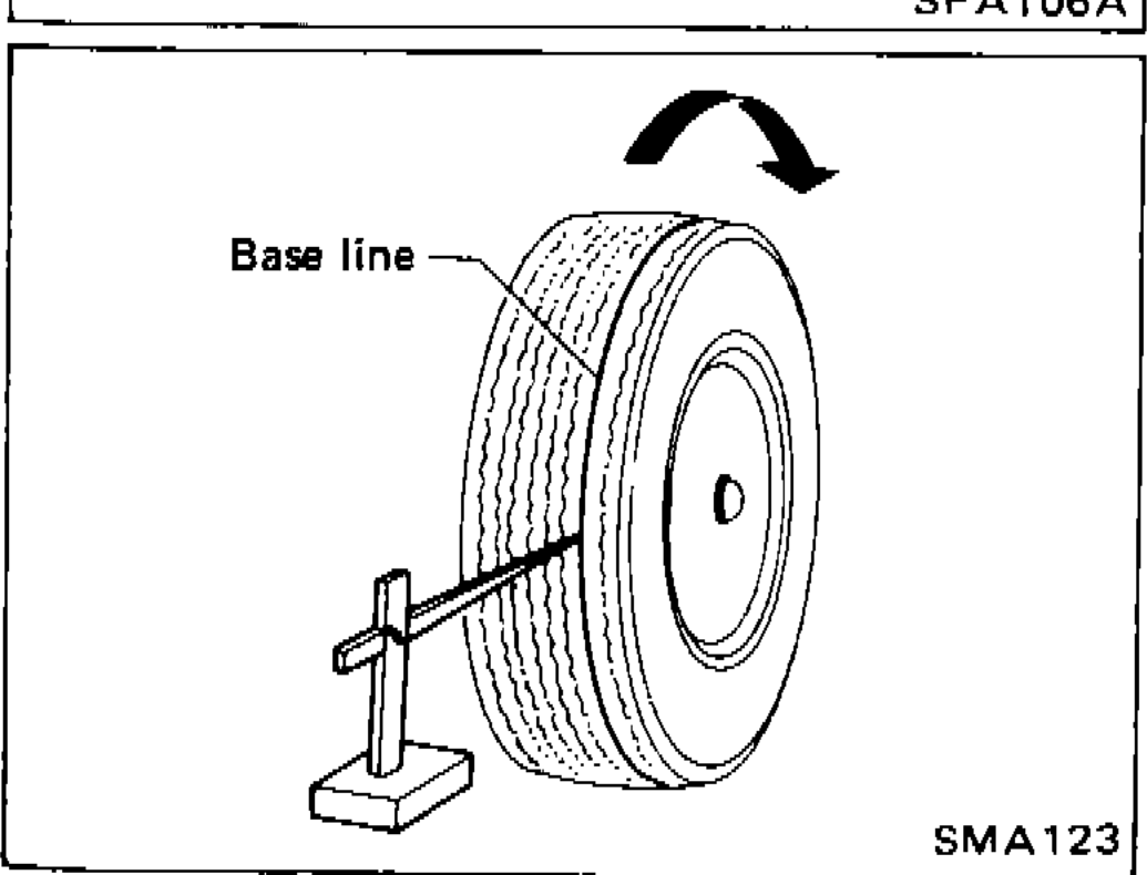 SMA123