
FUEL SYSTEM
FE-3parts diagramElectric fuel pump model noted for fuel pressure release procedure before disconnecting fuel hose.
WARNING
When replacing fuel line parts, be sure to observe the following:
• Put a "CAUTION: INFLAMMABLE" sign in workshop.
• Do not smoke while servicing fuel system. Keep open flames and sparks away from work area.
• Be sure to disconnect battery ground cable before conducting operations.
• Put drained fuel in an explosion-proof container and put lid on securely.
CAUTION
• For electric fuel pump model, before disconnecting fuel hose, release fuel pressure from fuel line. Refer to "Changing Fuel Filter" in MA section.
• Do not disconnect any fuel line unless absolutely necessary.
• Plug hose and pipe openings to prevent entry of dust or dirt.
• Always replace O-ring and clamps with new ones.
• Do not kink or twist hose and tube when they are installed.
• Do not tighten hose clamps excessively to avoid damaging hoses.
• When installing fuel check valve, be careful of its designated direction. (Refer to section EF & EC.)
• Run engine and check for leaks at connections.
Parts DiagramFig. fig1
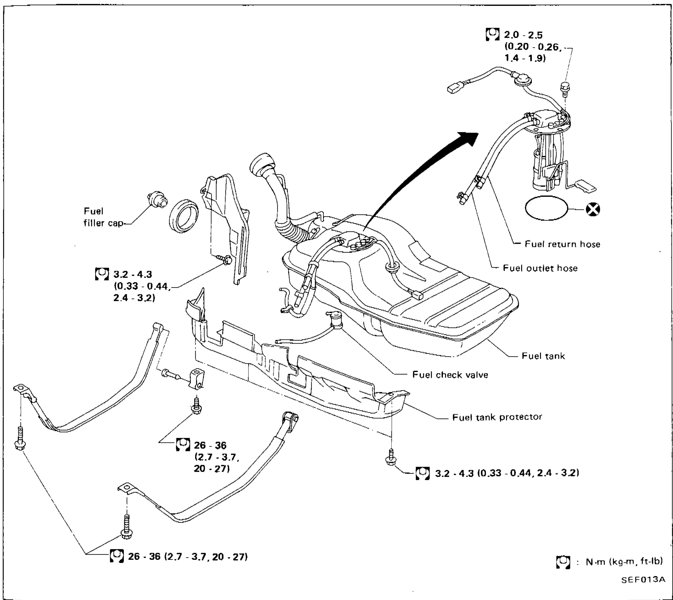
| Specification | Value |
|---|---|
| Fuel pump assembly mounting screws | 2.0 - 2.5N·m |
| Fuel filler neck clamp / hose clamp torque (upper area) | 3.2 - 4.3N·m |
| Fuel tank mounting bolt torque (front/lower left) | 26 - 36N·m |
| Fuel tank mounting bolt torque (rear/lower right) | 26 - 36N·m |
| Fuel tank protector bolt torque (right side) | 3.2 - 4.3N·m |
Fuel pump assembly mounting screws
2.0 - 2.5N·m
Fuel filler neck clamp / hose clamp torque (upper area)
3.2 - 4.3N·m
Fuel tank mounting bolt torque (front/lower left)
26 - 36N·m
Fuel tank mounting bolt torque (rear/lower right)
26 - 36N·m
Fuel tank protector bolt torque (right side)
3.2 - 4.3N·m